The Non-Inverting Op Amp: Precision Amplification Without Signal Distortion
The non-inverting operational amplifier (op amp) stands as a cornerstone of modern analog electronics, offering unparalleled precision in signal amplification without phase inversion. Unlike its inverting counterpart, this configuration preserves the original waveform while scaling its amplitude—a critical feature in audio systems, sensor interfaces, and medical instrumentation. Engineers rely on its stability and gain accuracy, but its true power lies in how it transforms raw input signals into clean, amplified outputs with minimal distortion.
At its core, the non-inverting op amp configuration amplifies signals while maintaining their polarity, making it ideal for applications where signal integrity is paramount. Whether in voltage followers, active filters, or precision rectifiers, this topology ensures that the output mirrors the input with only the desired gain applied. The absence of phase reversal simplifies circuit design in systems where signal inversion would introduce complications, such as in feedback loops or cascaded amplifiers.
The versatility of the non-inverting op amp extends beyond basic amplification. Its ability to handle both AC and DC signals with equal efficacy has cemented its role in high-fidelity audio equipment, where maintaining waveform fidelity is non-negotiable. Meanwhile, in industrial control systems, its robustness against noise and drift makes it indispensable for monitoring critical parameters. Yet, despite its widespread adoption, many engineers overlook the nuances of its operation—from gain stability to slew rate limitations—that can make or break a design.

The Complete Overview of Non-Inverting Operational Amplifiers
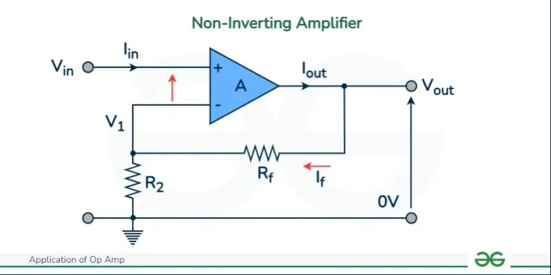
The non-inverting op amp configuration represents one of the most fundamental yet powerful arrangements in analog circuit design. By applying the input signal directly to the non-inverting terminal (+) while feeding a portion of the output back to the inverting terminal (−) via a feedback network, this topology achieves amplification without altering the signal’s phase. This direct connection to the input ensures that the op amp’s open-loop gain (typically in the range of 100,000 to 1,000,000) is harnessed to produce an output that closely follows the input, scaled by the closed-loop gain determined by the feedback resistors.What distinguishes the non-inverting configuration from its inverting counterpart is its inherent simplicity and stability. In an inverting op amp, the input signal is applied to the inverting terminal, requiring careful consideration of input impedance and signal grounding. The non-inverting setup, however, presents a high input impedance (approaching infinity in ideal conditions), which minimizes loading effects on the source signal. This characteristic is particularly valuable in applications where the signal source has limited drive capability, such as in sensor interfaces or high-impedance transducers.
Historical Background and Evolution
The origins of the operational amplifier trace back to the early 20th century, with the development of analog computers during World War II. Early op amps were bulky, vacuum-tube-based devices used primarily for mathematical operations—hence the name "operational amplifier." The invention of the transistor in the 1950s revolutionized op amp design, leading to smaller, more reliable solid-state amplifiers. By the 1960s, integrated circuit (IC) technology enabled the mass production of op amps like the 741, which became a standard in both industrial and consumer electronics.The non-inverting configuration emerged as a natural evolution of these early designs, offering a straightforward method to amplify signals without phase inversion. Early applications included audio amplification, where preserving the original waveform was critical, and instrumentation amplifiers, where precision and stability were paramount. As semiconductor technology advanced, op amps became faster, more accurate, and more power-efficient, expanding their use into high-speed data acquisition, medical devices, and wireless communication systems. Today, the non-inverting op amp remains a staple in analog design, with modern variants incorporating rail-to-rail outputs, low-noise architectures, and micro-power consumption for portable applications.
Core Mechanisms: How It Works
The operation of a non-inverting op amp hinges on negative feedback, where a portion of the output is fed back to the inverting terminal (−) to regulate the amplifier’s gain. The key principle at play is the op amp’s virtual short—the near-zero voltage difference between the inverting and non-inverting terminals, enforced by the amplifier’s high open-loop gain. When an input signal is applied to the non-inverting terminal (+), the op amp adjusts its output to ensure that the voltage at the inverting terminal (−) matches the non-inverting terminal’s voltage, minus the effect of the feedback network.Table of Contents
- The Complete Overview of Non-Inverting Operational Amplifiers
- Historical Background and Evolution
- Core Mechanisms: How It Works
- Key Benefits and Crucial Impact
- Major Advantages
- Comparative Analysis
- Future Trends and Innovations
- Conclusion
- Comprehensive FAQs
- Q: What is the primary difference between a non-inverting and an inverting op amp?
- Q: How does the closed-loop gain of a non-inverting op amp differ from its open-loop gain?
- Q: Why is the non-inverting configuration preferred in audio amplification?
- Q: Can a non-inverting op amp be used as a voltage follower?
- Q: What are the limitations of a non-inverting op amp in high-frequency applications?
- Q: How does temperature affect the performance of a non-inverting op amp?
- Q: What role does the feedback resistor play in a non-inverting op amp circuit?
- Q: Are there any common mistakes to avoid when designing with non-inverting op amps?
The closed-loop gain (\(A_{CL}\)) of a non-inverting op amp is determined by the ratio of the feedback resistor (\(R_f\)) to the resistor connected to ground (\(R_1\)), following the formula:
\[
A_{CL} = 1 + \frac{R_f}{R_1}
\]
This relationship means that the gain is always at least 1 (unity gain when \(R_f = 0\)), and it can be adjusted by varying \(R_f\) and \(R_1\). Unlike the inverting configuration, where the input signal is attenuated by the input resistor, the non-inverting setup amplifies the entire input signal, making it ideal for high-impedance sources. Additionally, the feedback loop stabilizes the gain, reducing sensitivity to variations in the op amp’s open-loop characteristics.
Key Benefits and Crucial Impact
The non-inverting op amp configuration is favored in a wide range of applications due to its inherent advantages over other amplifier topologies. Its ability to amplify signals without phase inversion simplifies circuit design, particularly in systems where signal polarity must be preserved. This feature is especially critical in audio systems, where phase distortion can degrade sound quality, and in sensor interfaces, where the output must accurately reflect the input measurement. Beyond phase preservation, the non-inverting op amp offers superior input impedance, which minimizes loading effects on sensitive signal sources.Another significant benefit is its stability in closed-loop configurations. The negative feedback inherent in the non-inverting design suppresses oscillations and reduces gain drift, making it reliable for precision applications such as data acquisition and medical instrumentation. Furthermore, the configuration’s simplicity allows for easy integration into complex systems, where multiple amplifiers may be cascaded without introducing phase shifts or signal degradation.
"In analog design, the non-inverting op amp is the Swiss Army knife—versatile, reliable, and capable of handling tasks from the simplest voltage follower to the most demanding signal conditioning." — Dr. John L. Choma Jr., Professor of Electrical Engineering, University of Southern California
Major Advantages
- Phase Preservation: The output signal maintains the same polarity as the input, eliminating the need for additional inversion stages in applications like audio amplification or sensor readouts.
- High Input Impedance: The non-inverting terminal draws negligible current, making it ideal for interfacing with high-impedance sources such as piezoelectric sensors or thermocouples without loading effects.
- Stable Gain: Negative feedback ensures that the closed-loop gain remains consistent despite variations in temperature, power supply, or component tolerances.
- Wide Dynamic Range: The configuration can handle both small and large signal amplitudes without distortion, provided the op amp’s slew rate and power supply limits are respected.
- Simplified Circuit Design: The absence of phase inversion reduces complexity in multi-stage amplifiers, as no additional inverting stages are required to restore signal polarity.
Comparative Analysis
While the non-inverting op amp excels in many applications, its performance must be evaluated alongside other configurations to determine the optimal choice for a given task. Below is a comparative analysis of the non-inverting and inverting op amp configurations, highlighting key differences in gain, input impedance, and typical use cases.| Parameter | Non-Inverting Op Amp | Inverting Op Amp |
|---|---|---|
| Gain Formula | ACL = 1 + (Rf/R1) |
ACL = - (Rf/Rin) |
| Input Impedance | Very High (Approaches Infinity) | Low (Determined by Rin) |
| Output Polarity | Same as Input (Non-Inverting) | Inverted Relative to Input |
| Typical Applications | Audio amplification, voltage followers, active filters, sensor interfacing | Signal conditioning, active filters, impedance matching, AC coupling |
Future Trends and Innovations
The evolution of the non-inverting op amp is closely tied to advancements in semiconductor technology and the growing demand for higher performance in analog circuits. One emerging trend is the integration of op amps into system-on-chip (SoC) designs, where mixed-signal architectures require precise amplification alongside digital processing. Modern non-inverting op amps now feature rail-to-rail inputs and outputs, enabling operation with low supply voltages—a critical advancement for battery-powered and portable devices.Another innovation is the development of low-noise, high-speed op amps, which are essential for high-resolution data acquisition and communication systems. These amplifiers leverage advanced fabrication processes, such as silicon-on-insulator (SOI) technology, to reduce thermal noise and improve bandwidth. Additionally, the rise of digital potentiometers and programmable gain amplifiers (PGAs) allows designers to dynamically adjust the gain of non-inverting configurations, enhancing flexibility in adaptive signal processing systems. As IoT and edge computing continue to expand, the non-inverting op amp will remain a critical component, bridging the gap between analog sensors and digital signal processing.

Conclusion
The non-inverting operational amplifier remains one of the most versatile and widely used configurations in analog electronics, offering a perfect balance of simplicity, stability, and performance. Its ability to amplify signals without phase inversion makes it indispensable in applications ranging from high-fidelity audio to precision instrumentation. As semiconductor technology advances, these amplifiers continue to evolve, incorporating features like rail-to-rail operation and ultra-low noise to meet the demands of modern electronic systems.For engineers and designers, understanding the nuances of the non-inverting op amp—from its gain characteristics to its feedback mechanisms—is essential for optimizing performance in real-world applications. Whether used as a voltage follower, a gain stage, or part of a complex signal conditioning chain, this configuration proves time and again that fundamental principles still reign supreme in analog design.
Comprehensive FAQs
Q: What is the primary difference between a non-inverting and an inverting op amp?
A: The primary difference lies in how the input signal is applied. In a non-inverting op amp, the input is connected to the non-inverting terminal (+), preserving the signal’s polarity. In an inverting op amp, the input is applied to the inverting terminal (−), resulting in a 180-degree phase shift in the output. Additionally, the non-inverting configuration offers higher input impedance, making it better suited for high-impedance sources.
Q: How does the closed-loop gain of a non-inverting op amp differ from its open-loop gain?
A: The open-loop gain of an op amp is its inherent amplification when no feedback is applied, typically ranging from 100,000 to 1,000,000. The closed-loop gain, determined by the feedback network (1 + Rf/R1), is significantly lower but highly stable due to negative feedback. For example, an op amp with an open-loop gain of 100,000 and a closed-loop gain of 10 will maintain a precise gain of 10 despite variations in the open-loop characteristics.
Q: Why is the non-inverting configuration preferred in audio amplification?
A: The non-inverting op amp is preferred in audio applications because it preserves the phase of the input signal, preventing phase distortion that can degrade sound quality. Additionally, its high input impedance minimizes loading effects on microphones or other audio sources, ensuring a faithful reproduction of the original signal. The configuration’s stability also reduces harmonic distortion, which is critical for high-fidelity audio systems.
Q: Can a non-inverting op amp be used as a voltage follower?
A: Yes, a non-inverting op amp can function as a voltage follower by setting the feedback resistor (Rf) to zero (or connecting the inverting terminal directly to the output). In this configuration, the closed-loop gain is 1, meaning the output voltage precisely follows the input voltage. Voltage followers are commonly used for impedance matching, buffering, and isolating stages in signal chains.
Q: What are the limitations of a non-inverting op amp in high-frequency applications?
A: At high frequencies, non-inverting op amps may encounter limitations such as reduced gain bandwidth, slew rate limitations, and increased phase shift due to parasitic capacitances. The op amp’s unity-gain bandwidth (the frequency at which the open-loop gain drops to 1) determines its high-frequency performance. For applications requiring high-speed amplification, selecting an op amp with a sufficiently high bandwidth and low output capacitance is essential to maintain signal integrity.
Q: How does temperature affect the performance of a non-inverting op amp?
A: Temperature variations can impact the performance of a non-inverting op amp by altering its open-loop gain, input offset voltage, and bias currents. Negative feedback helps mitigate these effects, but extreme temperatures may still cause drift in the closed-loop gain or introduce noise. High-quality op amps with low temperature coefficients are often used in precision applications to minimize these issues.
Q: What role does the feedback resistor play in a non-inverting op amp circuit?
A: The feedback resistor (Rf) in a non-inverting op amp circuit, along with the resistor to ground (R1), determines the closed-loop gain according to the formula \(A_{CL} = 1 + (R_f/R_1)\). By adjusting these resistors, designers can set the desired gain while maintaining stability. The feedback network also ensures that the op amp operates within its linear region, preventing saturation and distortion.
Q: Are there any common mistakes to avoid when designing with non-inverting op amps?
A: Common mistakes include improper grounding, which can introduce noise; incorrect resistor values leading to unstable gain; and exceeding the op amp’s slew rate or power supply limits, causing distortion. Additionally, failing to account for input bias currents in high-impedance circuits or neglecting to use decoupling capacitors for power supply stability can degrade performance. Always refer to the op amp’s datasheet for recommended operating conditions.
Leave a Comment
Comments are moderated before appearing. The data you submit is processed according to the Privacy Policy of Bevvy.